Official Assignment Description: 'add an ouput device to a microcontroller board and program it to do something'
I decided to hijack this week and work on my final project; the relevant component of that project is an interface with an LCD screen. I've used LCD screens a couple times in the past, but am always annoyed by the communication protocols and the number of pins you need to connect to it. A couple of weeks ago I noticed Sparkfun was selling an LCD screen with a built-in PIC that translated input serial communication to the built-in LCD controller. This seemed too good to pass up, so the first part of this week's project was an effort to learn how to communicate with it etc. The second part of this week's project (perhaps more challenging), was to develop a code that could do the following:
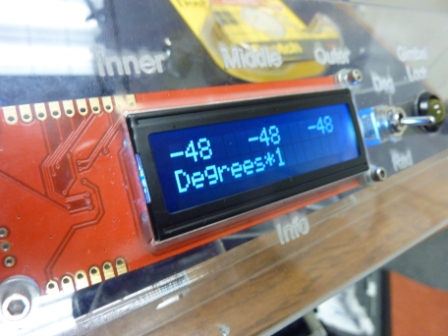
Step 1: Learning to communicate with the LCD screen was relatively simple at 9600 BAUD. The Arduino community
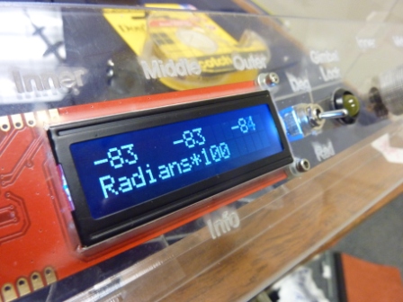
was pretty helpful in trouble-shooting. One annoying quirk was that there was no built-in way of handling floating point
numbers. I eventually just decided to multiply the floats by 100 and show their integer value (see 'Radians*100 below).
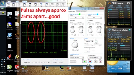
The PIC also required that you wait approximately 1ms between sending serial commands / strings...which I don't remember
being an issue on the standard LCD's.
Step 2: Realize I need faster communication than 9600bps and try to change it. The data sheet said I could just
write "control p" to the serial port to change to 38400bps, which seemed simple enough (see pdf file). (Oh, who's ever heard of sending
'control' in ASCII? Not me, but fortunately internet forums came to the rescue.) This turned out not
to be the case; half the time the LCD screen wouldn't recognize my commands, and half the time it would simply 'lock up.' Fortunately
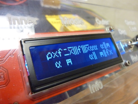
there is a reset command (which I used many times). In the end, I finally coaxed it to run at 19200bps, but need to tell my
serialSoft connection to run at 19300...which is odd because both the PIC and the ATmega are using crystals. Sigh. Below is
what it looks like when communication speeds are not synced.
SerLCD_V2_5.pdf